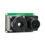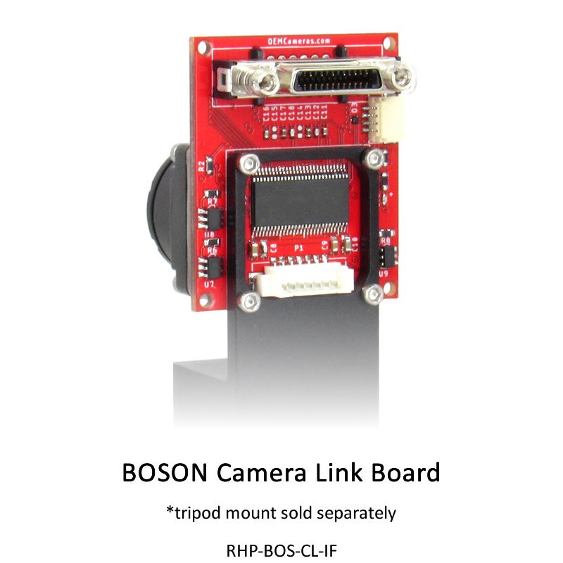

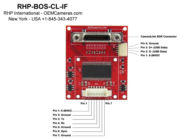
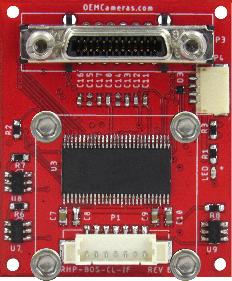
RHP Boson Camera Link Interface Board
- Camera Link SDR-26 Base Mode Video Output
- Wide input voltage range of 5-26VDC
- Multiple power inputs
- Reverse Polarity Protection
- Master / Slave Sync Option (30Hz Only)
- 3.3V TTL/UART Control
- USB Video and Control
- USB Video Support
- Allows for use with Boson Tripod Mount Adapter
$399.00
Description
Specifications
Downloads
Comparison
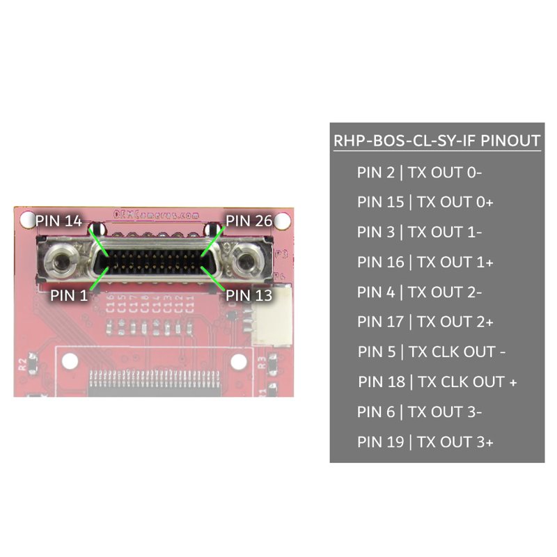
RHP-BOS-CL-SY-IF
Camera Link Module
The RHP Boson Camera Link Interface Board offers both versatility and power. Its SDR-26 Base Mode Video Output, combined with a wide input voltage range of 5-26VDC, makes it an ideal choice for many different applications. With multiple power inputs and Reverse Polarity Protection, it is a reliable option. Additionally, the Master/Slave Sync Option allows for even greater flexibility. The USB Video and Control, as well as the 3.3V TTL/UART Control, make managing every aspect an easy task. Moreover, this board is fully compatible with the Boson Tripod Mount Adapter.
![]()
Master Mode
With External Sync Master mode, a Boson camera sends output pulses that indicate to external equipment when frame data acquisition has begun. This output will be at approximately 60 Hz.
![]()
Sync Mode
With External Sync Master mode, a Boson camera sends output pulses that indicate to external equipment when frame data acquisition has begun. This output will be at approximately 60 Hz.
![]()
Slave Mode
When the External Sync State is in Slave mode, external equipment sends reference pulses to the Boson camera which begin the acquisition of each video frame by the Boson camera. The input signal rate ideally matches the nominal video acquisition rate of the Boson camera.
Please Note: External Sync is disabled on Boson ≤9Hz Cameras.
The use of external sync on these cameras is not supported because pulses cannot be correlated to a specific output frame because of the way the reduced frame rate video is created. If attempted, the camera will reject commands to begin external sync mode.
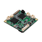
Camera Link + Sync (30Hz Only)
It is also possible to enable master/slave sync communication with the RHP-BOS-CL-SY-IF Camera Link module.
The Master/Slave Sync Option allows the Boson to be connected in parallel with a 3.3v buffered port.
The BOS-CL-SY-IF’s microcontroller circuit provides a 3.3V TTL/UART (Universal Asynchronous Receiver/Transmitter) Control to transmit and receive serial data.
![]()
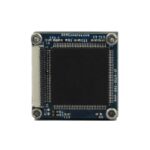
Designed with
Implementation in mind
Our development team works hard to create functional and practical products with implementation.
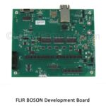
The BOS-CL-SY-IF design allows it to be mounted to the FLIR Boson Tripod Bracket. which provisions for standard 1/4″ x 20 tripod mounting.
The footprint of the tripod bracket can easily be adapted for custom mounting use.
![]()
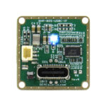
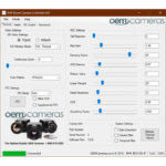
Command and Control
The camera uses serial communication at 921600 Baud by creating a virtual COM Port on your computer for USB communications.
The BOS-CL-SY-IF USB Video and Control can be performed through the FLIR Camera Controller Graphical User Interface (GUI) , which enables remote command and control of Boson.
![]()
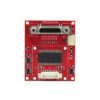
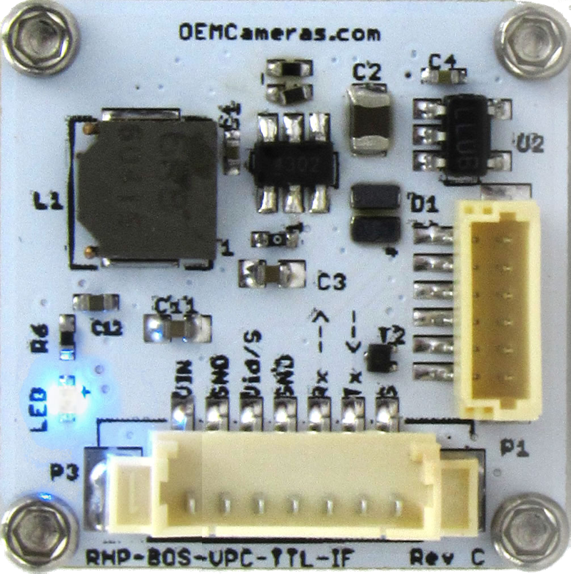
Power Protection
Reverse Polarity Protected
With the intelligent polarity sensing protection, the RHP-BOS-CL-SY-IF can be powered in multiple ways:
- 4-pin JST to USB cable (provided) to allow standard 5VDC (up to 26VDC).
- 7-pin pico blade connector with voltages ranging from 5-26VDC for both the camera and interface.
| Operating Temperature Range | |
|---|---|
| Video Output Type |
SDR-26 |
| Voltage Input |
5-26 Volts DC |
- RHP-BOS-TTL-IF
- RHP-BOS-CL-SY-IF
Synchronization |
$149.00
RHP-BOS-TTL-IF
|
$399.00
RHP-BOS-CL-SY-IF
|
Purpose |
Video, Power, Communication | Video, Power, Communication |
Power |
5 to 26Volts DC Input | 5 to 26Volts DC Input +Multiple Power Inputs |
Reverse Polarity Protected |
||
Connection |
USB or TTL Communication | Master/Slave Sync Option +3.3V TTL/UART Control |
Outputs |
2 Composite Video Outputs | Camera Link SDR-26 Base Mode Video Output |
Video Support |
Stream Video to PC via USB | USB Video and Control |
Sync In/Out |
Ext. Video SYNC In/Out Optional | Ext. Video SYNC In/Out Optional |
| RHP-BOS-TTL-IF | RHP-BOS-CL-SY-IF |